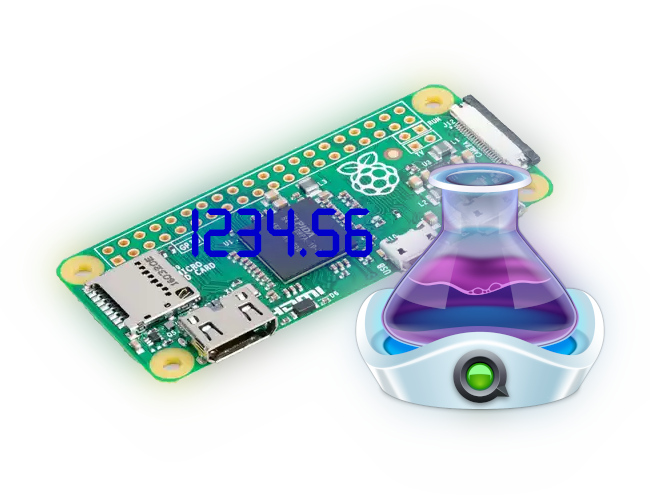
A Raspberry Pi Zero play head for QLab
This is a little project that I have had on the back burner for a little while. I recently had a little more time in my schedule and managed to get to a working state. So what is it? It is a Raspberry Pi Zero with a TM1637 screen on it which shows us the cue number of the playhead for a QLab session on an Apple mac attached via USB.
Why would I want this?
I work professionally in theatre on a (slightly off) West End show. We use a piece of software called QLab to playback and control the hardware for sound and lighting. QLab is very much the industry standard for this use case. However, there are rare situations where the software can fail. Due to this it is very common to have a change over device within the system that allows us to switch all of the sound and control from a main to a backup mac. Sometimes the two mac can get out of sync and you have no way of knowing without toggling between the two different video outputs. An easy solution would be to put a second screen on the backup mac but a lot of control positions are often quite small or located within the audience where the excess light is undesirable. There are a few software based solutions out there if you know where to look but this again relies on there being another computer with a screen that you don’t mind running an app on.
Why is your solution better?
The project started when one of my old Sound No. 2s asked me if it was possible to run the software solution (yes the show I work on has the spare computer situation) on a Raspberry Pi with a screen. After thinking about it for a little while I pointed out that the app that we use was mac only app so no it wouldn’t. It also was created by the sound designer and is hard coded to look for our backup QLab mac so unless you always put a mac on that IP address it’s not going to work in another network. After thinking a little longer on it I realised that actually a Raspberry Pi Zero was a perfect candidate to make this a hardware device.
Why is the Raspberry Pi Zero perfect?
Unlike other Raspberry Pis (when I started thinking about creating this project) the Pi Zero can be used in what’s called gadget mode. This means that it can imitate other types of device over its USB port. This means that if connected to another computer it can be seen as an input device (mouse or keyboard), a MIDI or an ethernet device. Why is this useful? Well we can get the Pi to imitate a ethernet device and then (with some DHCP wizardry) communicate with QLab using OSC commands. This project could, however, be adapted for a full size pi and use the built in NIC to access the QLab session over a network rather than directly from the USB port. I would suggest that you skip the DHCP server part as this would possibly wreak havoc on your LAN.
What would we like the device to do?
This is the list that I decided to work from when starting the project:
- Must be plug and play
- Must create a point to point network
- Use and 7 segment type display to show the selected cue number
- Must use a single USB cable in direct mode1
- Must have an adjustable refresh rate
- Have controllable brightness
- Have the settings changed via OSC messages from QLab
- Should default back to standard config when rebooted
There are a few other ideas that I had but I thought that this was a good enough list to try and start with. I was on the fence about whether the pi playhead should remember the setting you want but in the balance, I felt, it is better to always know what state the system is in when it boots. What do I mean by this? Well if I were to take my pi playhead to another mac I know it will default back to the “factory” refresh rate and brightness. An easy way to configure the pi playhead would be to add an QLab group cue to your show setup that then pushes your desired settings onto the pi playhead whilst you are doing your rig check. Maybe I’m wrong. Write a comment below and let me know.
Setting up the hardware
To make this project you will need:
- 1 x Raspberry Pi Zero W
- 1 x 8GB or higher SD card
- 1 x 6 digit TM1637 display
- 1 x Data micro USB cable
- Some wire and a soldering iron or any other method of attaching the display to the Pi
The first place to start is by installing your Raspberry Pi. For the sake of my sanity right now I am not going to write a Raspberry Pi getting started guide. This may change in the future if I get extremely bored. Here is the official documentation from Raspberry Pi themselves. I would, however, recommend combining this tutorial with the newer install method recommended by Raspberry Pi. For this project I picked the Raspberry Pi OS Lite option as I was looking for an easy life. Pretty much any of the OSs should work for this project but installation methods may vary. The three main reasons I went with vanilla Raspberry Pi OS Lite is that:
- Given it is made but the creators of the hardware you would hope it would be most compatible
- I didn’t want an OS with a GUI as this is intended to be a screen-less device so why use the resources?
- I am more familiar with Debian based varieties of Linux. The only things I would note is that configuring your Pi with the correct Wi-Fi and any SSH keys you may have in the Raspberry Pi imager software is much easier than trying to do it later.
Gadget mode
After that we need to get the Pi into gadget mode. Again for my sanity I’m going to suggest following the second of the two install tutorials above. Once you have successfully gotten the Pi into gadget mode we will give the USB interface a static IP address.
Edit the file /etc/network/interfaces in your favourite text editor and add the following to the bottom of your file:
1
2
3
4
5
6
7
allow-hotplug usb0
iface usb0 inet static
        address 192.168.123.1
        netmask 255.255.255.252
        network 192.168.123.0
        broadcast 192.168.123.3
        gateway 0.0.0.0
The entire file will now probably look something like this:
1
2
3
4
5
6
7
8
9
10
11
# interfaces(5) file used by ifup(8) and ifdown(8)
# Include files from /etc/network/interfaces.d:
source /etc/network/interfaces.d/*

allow-hotplug usb0
iface usb0 inet static
        address 192.168.123.1
        netmask 255.255.255.252
        network 192.168.123.0
        broadcast 192.168.123.3
        gateway 0.0.0.0
This bit of configuration tells the interface to wait until it has detected that it has been plugged in and sets an IP address of 192.168.123.1/32 (a /32 network only has 2 assignable IP addresses in it. 1 for the Pi and 1 for the QLab mac). This IP address could be anything that takes your fancy. I have made an assumption that your USB gadget has been assigned on USB0 and will continue to make this assumption as if you have managed to get it to something else you probably know how to make sure it works.
Configuring the DHCP server
Next we move on to configuring the DHCP server. Check that it is installed by running sudo apt install dnsmasq. Now in your favourite text editor open /etc/dnsmasq.conf and add the following lines at the bottom of your file:
1
2
3
4
5
interface=usb0
bind-dynamic
domain-needed
bogus-priv
dhcp-range=192.168.123.2,192.168.123.2,255.255.255.252,120
The only part that we are really interested in is the last line. This sets the start and end of the DHCP pool to 192.168.123.2 (we only want 1 address for the QLab mac). The subnet mask to 255.255.255.252 (a /32 network). And the lease time in seconds.
A note on the lease time. As you can see from the code snippet this is set to 120s or 2 minutes. This unfortunately is the shortest duration that you can set. This does mean that you will need to wait for at least two minutes if you are trying to swap the playhead to another mac.
For the most part this should be the majority of the setup we need to do on the pi. Next we look at attaching the display.
Attaching the display
When I originally started this project I bought a 4 digit display from eBay. It worked great but I found out after jumping in that the cheaper displays only do either a : between the second and third digits or an . between every digit. Typically I got the former that I didn’t want. However, it was very easy to swap out the 4 digit display for the 6 digit version. I picked a blue display as the seller I purchased from had them in stock and I was impatient and didn’t want to wait. There’s very little to these displays so as long as they have the TM1637 chip you should be good to go.
I decided that, for me, the best way to attach the display to the pi was to solder it directly on to the board. This may not be suitable for you but, even though I had purchased the pi for another project, I decided that I was going to commit this pi to this project. I also have easy access to the tools I need to remove the display if I ever decided I wanted to use the display for another project. There are other methods of attaching the display. If you already have headers installed on you pi then you could use dupoint cables to hook it up (the display I ordered came with headers in the box albeit not actually attached).
The pinout required to hook the display up is as follows:
| pi pin | display | purpose |
|---|---|---|
| GPIO5 | CLK | Clock |
| GPIO3 | DIO | Data |
| 3.3V (or 5V) | VCC | Power |
| GND | GND | Ground |
Note that you will need to pick a voltage that matches what your display requires
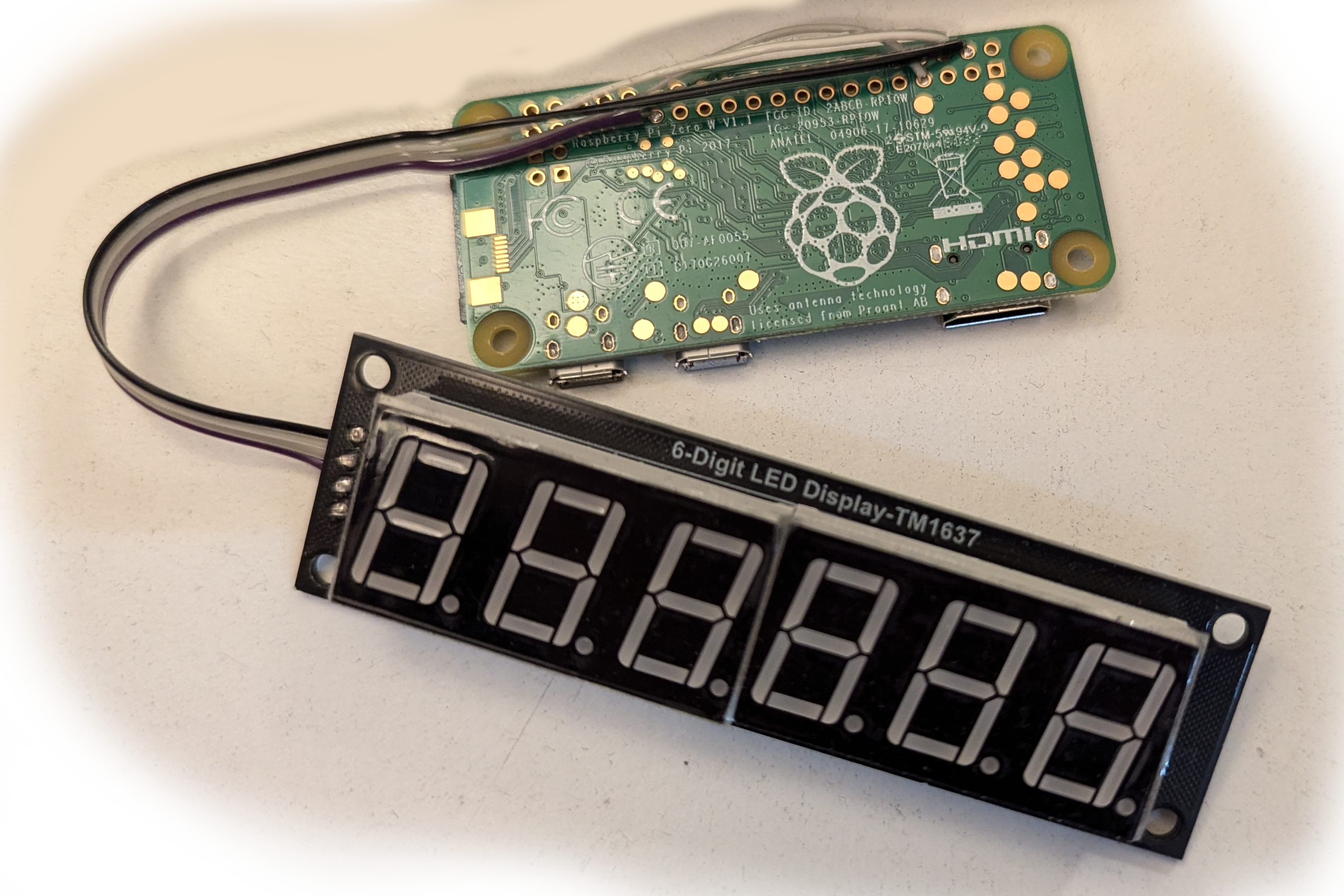
This is nice and simple and should take someone who is electronically minded about 5 minutes to do. (I managed to do it twice very quickly when I swapped from the 4 to 6 digit display).
Now for some software
Now we have the hardware and system setup for what we want its time to start looking at the app we are building to tie this all together. I decided to write this project in python (and version 3 at that). Why? For two reasons. The first is that python is shipped with all (as far as I am aware) Linux distros. Secondly I adapted bits of this from another project I made to control Blackmagic design devices from QLab using appleScripts to call python (2.7 come on apple you could upgrade this) scripts. If you are using Raspberry Pi OS and you have internet access on the pi then this next step is quite easy.
First off lets check that you have python which python3, the python package manager which pip3 and git which git are installed. If these commands return a path then we’re all good to go. If you get something that follows “which: no python3 found in (…)” then unfortunately you don’t have them installed. If this is the case the Google is probably your friend.
Navigate to the folder that you would like to install the project to and run the following command git clone https://github.com/allaway-tech/pi-playhead. This will then have the pi reach out to the the GitHub repository and download the latest version of the code.
To get the project running we need to run the following command from within the project directory pip3 install --requirement ./requirements.txt. This will then reach out to the python servers and install any packages that I decided to use. Now we can cross our fingers and run python3 LED.py and if everything is good your screen should light up and show the start up including the version number of the pi playhead code.
Now the only thing left to do is make the script start when the pi boots. This is a very easy step but I hit a slight speed bump during this step. When I was testing I thought to myself “I want to start this on boot. Let’s do that as root so it will all be hunky dory.”. This line of thought turned out to be wrong. You need to add the following line to the crontab of whatever user you have just tested the project on. If you don’t, like I did, then the script will fail to run and you’re more than likely to not know why as the error will disappear very quickly off your screen (if you are even using one) very quickly. It turns out that as we haven’t run the pip3 command as root then the dependencies aren’t installed for root and therefore it can’t run the script.
What does the script actually do?
The script is broken into two main sections which can be seen in the two function (def sections) near the bottom of the script. The first is the osc_client section that starts by sending an IMCP ping to the host to see if it is alive and then if it get a positive reply it requests the playhead position from QLab or updates the display to say NOQLAB if the ping times out (usually indicating the host is not present). The second function is the osc_server that listens out for replies from QLab and then handles those incoming OSC messages. The script actually runs in two threads meaning that it can both listen for replies and continue to pester QLab at the same time. You could run it in a single thread and have the osc_server listen after every time the osc_client sends a request but you run the risk of missing a reply. The pi zero also has more than enough resources to handle both sending and listening at the same time so why wouldn’t we?
Other than those two main functions there are a few at the top of the script that handle the data from the incoming OSC messages as well as writing that data to the display. These are all fairly straight forward and probably the only function of note is the def swap(segs): function that maps the digits into the correct order for a six digit display. This function is lifted straight from the examples in the TM1637 library.
A note about the code
I have been on the fence for a while about whether I should compile the python scripts and then just release the python binaries. If I did this I would also not make the source code publicly accessible. However, I personally get very annoyed by other projects that do this. I made this project for a bit of fun on the side and do not intend to monetise it in anyway. However, this also means I am providing no support with it either. If you find issues the please submit an issue on GitHub and I will try to have a look at it if I have the time. If you know how to fix it or just fancy having a go then by all means fork the repo and try to fix it yourself. If you do manage to fix it please consider submitting a pull request as it may also fix a problem for someone else. The source code can be found at this repo
Footnotes
A note about “direct” mode
The eagle eyed of you may notice that in the specification of the device I used the term direct mode. This is currently how the device operates but I have been kicking an idea around that you may be able to attach a USB ethernet connector to the pi and then get the playhead data from a mac that is elsewhere. Why would this be useful? You could have 3 of these pi playheads and use them as such:
- 1 for the backup QLab playhead for the sound op
- 1 for the main QLab playhead for the DSM
- 1 for the backup QLab playhead for the DSM
Another option is that if you know your mac will always boot the QLab session on load an you don’t actually need to access the gui you could connect 2 playheads, 1 to each mac, and then just use those display further reducing the number of screens required. ↩︎